Fracturing | Choke & Kill | Cementing Manifolds

High Pressure Manifolds: Fracturing, Choke & Kill, Production

A high pressure manifold is a collection of valves, pipes and fittings that distributes or controls the flow of high-pressure fluids. Different types of manifolds serve different functions: fracturing manifolds distribute frac fluid, choke & kill manifolds provide well control, and production manifolds gather well flow.

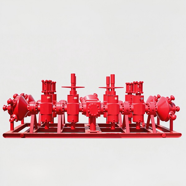
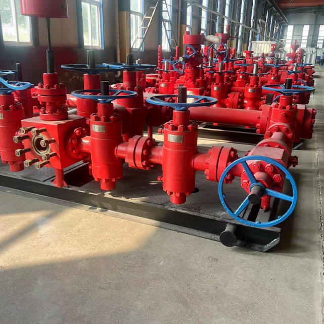
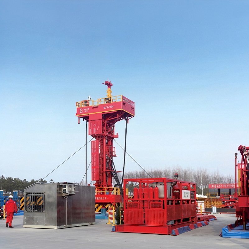
High pressure manifold for fracturing and well control

Main Types of High Pressure Manifolds

Fracturing Manifold

The fracturing manifold (or frac manifold) distributes high-pressure fracturing fluid from multiple pump trucks to the wellhead. It typically has 4-8 pump inlets and one or two outlets to the well. Consists of heavy-duty gate valves, tee pieces, and a main header. Pressure ratings are typically 10,000-15,000 psi. The frac manifold is critical for safe and efficient hydraulic fracturing operations.

Choke & Kill Manifold

The choke and kill manifold is used for well control during drilling and workover operations. The choke line controls flow during well kick procedures. The kill line pumps heavy mud to kill the well. Consists of gate valves, choke valves, pressure gauges and connecting piping. API 16C certified. Pressure ratings typically 5,000-10,000 psi.

Cementing Manifold

The cementing manifold distributes cement slurry from the cementing unit to the wellhead. It controls the flow of cement and spacer fluid during primary and remedial cementing operations. Consists of gate valves, check valves, and pressure gauges. Pressure ratings typically 5,000-10,000 psi.

Production Manifold

The production manifold (or gathering manifold) collects production from multiple wells and routes it to processing facilities. It has inlet connections from each well and outlet connections to the production separator or processing plant. Consists of gate valves and pressure control equipment. Pressure ratings typically 1,000-5,000 psi.

Fracturing Manifold: Detailed Overview

The fracturing manifold is the most demanding application for high pressure fluid control equipment:

Key Components

  • Main header: The main pipe that carries the fracturing fluid
  • Pump branches: 4-8 inlet branches from pump trucks
  • Outlet branch: 1-2 outlets to the wellhead
  • Gate valves: Heavy-duty gate valves on each branch
  • Tee pieces: Connections between branches and header
  • Pressure gauge: Monitors manifold pressure

Specifications

  • Pressure rating: 10,000 - 15,000 psi (70 - 105 MPa)
  • Flow rate: Up to 100+ bbl/min total flow
  • Pump connections: 2" or 3" hammer unions
  • Body material: 4130/4140 alloy steel, quenched and tempered
  • Valves: 2" or 3" gate valves, 10,000-15,000 psi rated
  • Standard: API 6A

Choke & Kill Manifold: Detailed Overview

The choke and kill manifold provides well control during drilling and workover:

How It Works

  • Choke line: Routes flow from the well through a choke valve
  • The choke restricts flow, controlling well pressure
  • Kill line: Routes heavy mud from the pump to the well
  • The kill line increases hydrostatic pressure to stop the flow
  • Used in conjunction with the BOP stack for well control

Key Components

  • Choke valves: Adjustable and positive chokes
  • Gate valves: Isolate branches for maintenance
  • Pressure gauges: Monitor well and manifold pressure
  • Accumulator: Provides hydraulic pressure for BOP operation
  • Standpipe: Connects to the rig's mud system

Manifold Pressure Ratings & Applications

Manifold Type Pressure Rating Flow Rate Typical Application
Fracturing Manifold 10,000 - 15,000 psi 40 - 100+ bbl/min Hydraulic fracturing operations
Choke & Kill Manifold 5,000 - 10,000 psi 10 - 50 bbl/min Drilling well control, workover
Cementing Manifold 5,000 - 10,000 psi 5 - 20 bbl/min Cementing operations
Production Manifold 1,000 - 5,000 psi Varies by well Production gathering, processing

Key Design Considerations

Erosion Resistance

Fracturing fluid contains sand and proppant, which causes erosion. Manifolds must be designed to handle abrasive flow. Valve internals are often hard-faced with Stellite or tungsten carbide. Wall thickness is increased in high-velocity areas. Regular inspection for erosion is essential.

Fatigue Life

Manifolds are subjected to repeated pressure cycling during operations. This can cause fatigue cracking, especially at welds and tee connections. Proper design (radiused corners, smooth transitions) and material selection are important. Pressure cycling analysis should be performed for critical applications.

Accessibility & Maintenance

Manifold design should allow easy access to valves and fittings for maintenance. Gate valves should be easy to operate. Spare valves should be readily available. The manifold should be laid out so that one branch can be isolated while others continue operating.

Frequently Asked Questions About High Pressure Manifolds

What is the difference between a fracturing manifold and a choke & kill manifold?

A fracturing manifold distributes high-pressure frac fluid from multiple pumps to the wellhead during hydraulic fracturing. It handles very high flow rates (40-100+ bbl/min) and high pressures (10,000-15,000 psi). A choke & kill manifold is used for well control during drilling and workover. It has lower flow rates (10-50 bbl/min) and lower pressure ratings (5,000-10,000 psi). They serve completely different functions.

How many pump connections does a typical fracturing manifold have?

Typical fracturing manifolds have 4, 6 or 8 pump branches. The number depends on the size of the frac operation. A standard shale gas frac job might use 6-10 pump trucks. Larger jobs may use more. The manifold must have enough branches to accommodate all the pumps being used. Some manifolds have redundant branches for backup.

What materials are used for fracturing manifolds?

Fracturing manifolds are typically made from high-strength alloy steel (AISI 4130, 4140 or 4145), quenched and tempered for high strength. Valve internals are hard-faced with Stellite or tungsten carbide to resist erosion from sand-laden fluid. For sour service, materials must meet NACE MR0175 requirements. The body material must have sufficient wall thickness to handle the pressure plus an erosion allowance.

How often should manifolds be inspected?

High pressure manifolds should be inspected before each job for visible damage. More thorough inspections (ultrasonic thickness testing, magnetic particle inspection for cracks) should be performed periodically —typically every 3-6 months or every 500-1,000 operating hours. Erosion is the most common failure mode, so wall thickness measurements are critical. Valve packing should be checked and replaced as needed.

Can you design custom manifold configurations?

Yes. We regularly design custom manifolds for specific applications. Provide us with your flow requirements, pressure rating, space constraints, and any special requirements (sour service, offshore, etc.), and our engineering team will design a manifold that meets your needs. We provide complete drawings, material specifications, and testing documentation with each custom design.

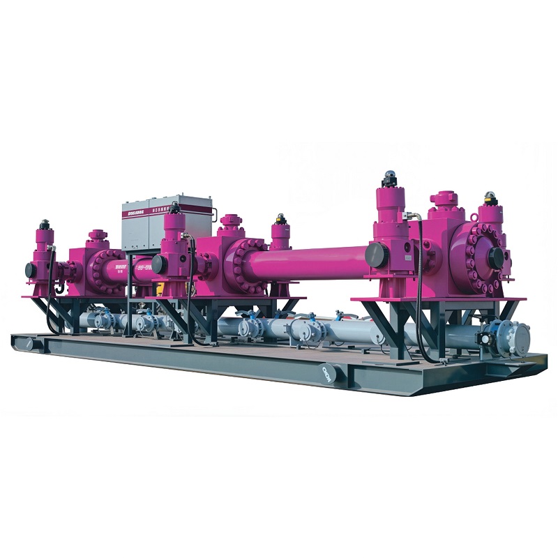
Need a High Pressure Manifold?

Tell us your required type (fracturing, choke & kill, cementing, production), pressure rating and flow requirements. Our engineering team will recommend the optimal manifold configuration and provide a detailed quotation within 48 hours.