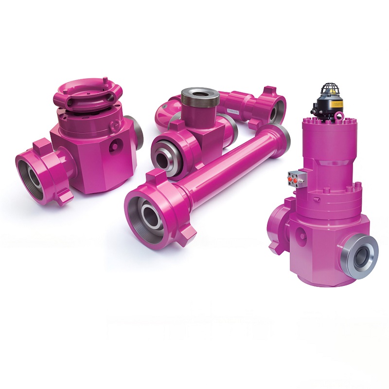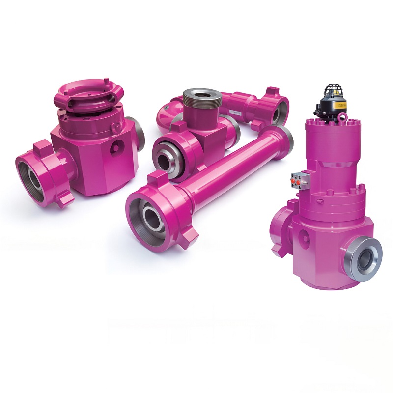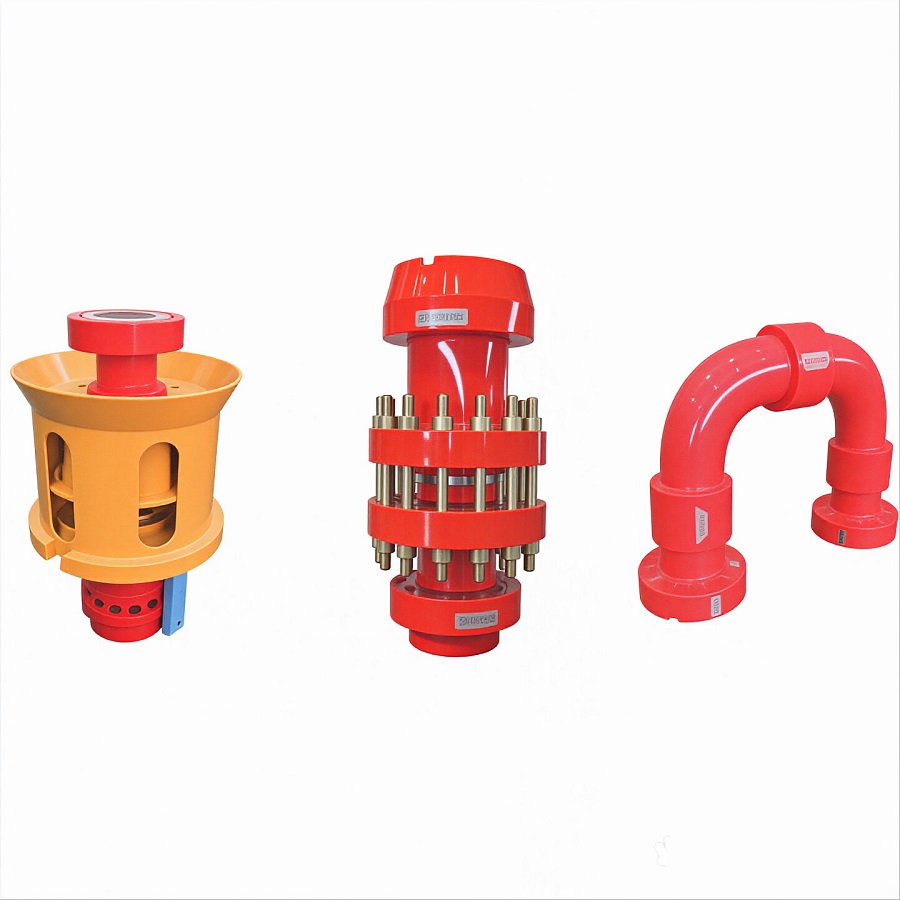
Wellhead & Christmas Tree
The starting point. The wellhead and Christmas tree control flow from the well. This is where the production fluid first emerges from the ground. Pressure and flow rate are controlled by the choke valve on the tree.
Surface high pressure fluid control equipment refers to the valves, fittings, manifolds and piping that control the flow of produced fluids at the surface. This includes the production manifold, flowlines, separators, metering equipment and processing facilities that make up a production surface facility.
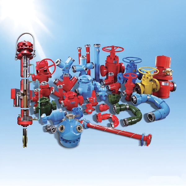
A typical production surface facility consists of several stages, each with its own fluid control equipment:
The starting point. The wellhead and Christmas tree control flow from the well. This is where the production fluid first emerges from the ground. Pressure and flow rate are controlled by the choke valve on the tree.
The flowline transports production fluid from the wellhead to the production manifold or separator. Flowlines can be above-ground or buried. They are typically high-pressure steel pipe with flanged or threaded connections.
The production manifold gathers production from multiple wells and routes it to processing. It has inlet connections from each well and outlet connections to the separator or processing facility. Gate valves on each branch allow individual wells to be isolated.
The separator separates the production fluid into oil, gas and water phases. It is a pressure vessel that uses gravity to separate the phases. The separated oil, gas and water are then routed to further processing or storage.
Metering equipment measures the flow rate and volume of each phase. This includes oil meters, gas meters and water meters. Accurate metering is essential for production accounting and allocation between wells or operators.
Further processing equipment: heater treaters, dehydrators, compressors, pumps. The final products (oil, gas, produced water) are transported to storage or export via pipeline, truck or tanker.
The production manifold is the central fluid control point at the surface facility:
Tubing: Small-diameter pipe for individual well flowlines. 2" - 4" typical. Gathering line: Larger pipe that collects from multiple flowlines. 6" - 12" typical. Trunk line: Main pipeline that transports production from the field to processing. 12" - 24"+ typical.
Carbon steel: Standard for most flowlines. A106 Gr B, API 5L Grade B. Stainless steel: For corrosive service (high CO2, H2S). 304, 316L, duplex. Composite pipe: Fiberglass or reinforced composite for corrosive or abrasive service.
Flanged: API 6A flanges for high-pressure, easy disconnection. Threaded: API line pipe thread (LP) for smaller sizes. Welded: Permanent weld connections for long-distance gathering lines. Clamp connectors: Quick-connect hammer unions for temporary or service connections.
Separates production fluid into oil, gas and water. Uses gravity separation: gas rises to the top, water sinks to the bottom, oil stays in the middle. The three phases are drawn off through separate outlets. Pressure vessels are designed and stamped to ASME Boiler and Pressure Vessel Code.
Combines heating and separation to break oil-water emulsions. The heater treater heats the production fluid to reduce viscosity and help separate water from oil. Used for heavy oil or emulsified production. Includes a fire tube or electric heating element.
Safety valve that opens automatically when pressure exceeds the set point. Protects equipment and piping from overpressure. PRVs are required on all pressure vessels and piping systems. They are sized to handle the maximum expected flow and must be regularly tested.
Reduces and controls pressure in a piping system. Used to reduce high wellhead pressure to a lower, controlled pressure for processing equipment. Pressure regulators maintain a constant downstream pressure regardless of upstream pressure variations.
Emergency shutdown valve that closes automatically in an emergency. ESD valves are installed on critical flow paths and can be triggered by pressure, temperature, or manual activation. They provide a fail-safe way to isolate the facility.
Browse our surface high pressure fluid control equipment lineup. All products are API certified and available in various configurations.
Wellhead equipment is the assembly at the top of the well that suspends the casing and tubing and provides pressure containment. Surface equipment refers to everything downstream of the wellhead: flowlines, manifolds, separators, processing equipment. In other words, the wellhead is the interface between the well and the surface facility, and surface equipment is the facility itself.
The number of wells depends on the manifold size and the total flow rate. A small production manifold might handle 2-4 wells. A large manifold can handle 10-20+ wells. The limiting factor is the header pipe size and the total flow rate. If the total flow exceeds the manifold's capacity, you need a larger manifold or multiple manifolds.
The pressure rating depends on the wellhead pressure and the processing requirements. Most production surface equipment operates at 1,000 - 3,000 psi. High-pressure wells may require 5,000 psi or higher. Always choose a pressure rating that exceeds the maximum expected operating pressure, plus a safety margin. It is better to over-specify than under-specify.
API 6A covers wellhead and Christmas tree equipment. API 6D covers pipeline valves. At the surface facility, equipment near the wellhead (Christmas tree, production tree) is typically API 6A. Equipment further downstream (gathering lines, processing piping) is typically API 6D. The boundary between the two standards is usually at the production manifold or the first block valve after the tree.
We provide individual surface equipment components: manifolds, valves, fittings, separators. For complete facility design, we work with engineering firms that specialize in surface facility design. We can supply all the fluid control equipment specified by the engineering design. Provide us with the design specifications and we will quote the required equipment.
Tell us your well count, expected flow rates and pressure requirements. Our engineering team will recommend the optimal surface equipment configuration and provide a detailed quotation within 48 hours.